


External dimensions on the plan
Several Revit applications are running. Choose one:
Icon


Related news and articles
Using
The plugin allows you to automatically create exterior dimensions on a floor plan according to a specified configuration. Only horizontal and vertical walls, as well as grids, are processed. The configuration determines the sides of the plan for which dimensions will be created and the parameters of each dimension chain.
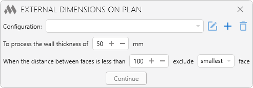
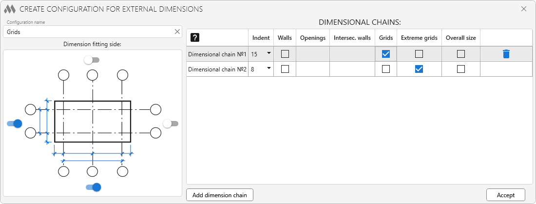
When the plugin is started for the first time, you must create a configuration by clicking  :
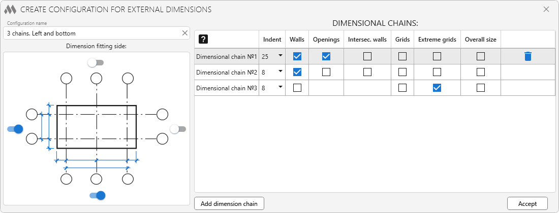
In the upper-left part of the window is a field for entering the configuration name.
Below is a list of the plan sides for which dimensions will be created. Use the toggle next to a side name to enable or disable it. At least one side must be selected to create a configuration.
On the right side of the window is the table of dimension chains for the current configuration. The configuration must contain at least one dimension chain.
The following properties can be specified for each dimension chain:
Ident – the distance between the dimension line and the previous element. For the first dimension chain, the offset is measured from the outermost selected wall. For subsequent chains, it is measured from the previous dimension chain. The value is specified in millimeters at actual size, so the actual offset in the view depends on the plan scale.
Walls – creates dimensions based on the overall extents of walls oriented in the selected direction. Vertical walls are used for the Left and Right directions, while horizontal walls are used for the Top and Bottom directions. When this property is enabled, the Openings and Intersecting Walls properties become available.
Openings – creates dimensions for wall openings in the selected direction.
Intersecting Walls – creates dimensions for walls that are perpendicular to the selected direction and intersect the walls oriented in that direction.
Grids – creates dimensions for grids that are perpendicular to the selected direction.
Extreme grids – creates dimensions only for the outermost grids that are perpendicular to the selected direction. When this property is enabled, dimensioning walls in the current dimension chain becomes unavailable.
Overall size – creates a single overall dimension in the selected direction. The overall dimension is determined as the distance between the outermost faces of the outermost walls. When this parameter is enabled, all other parameters of the current dimension chain become unavailable.
The last column of each dimension chain contains a delete button  . It is displayed only for the chain currently selected in the table.
Add dimension chain – adds a new dimension chain to the table. Chain names are assigned automatically and are used only for display in the list.
Accept – closes the window and saves the configuration settings.
The plugin window contains configuration controls and general processing settings:
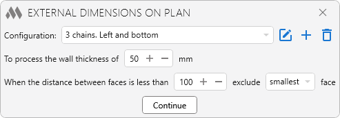
At the top of the window is a drop-down list of the created configurations. Configurations can be edited  (a window similar to the configuration creation window will open) and deleted
 using the corresponding buttons.
To process the wall with thickness of … mm – specifies the minimum thickness of walls included in processing. This allows you to exclude, for example, exterior finish walls created as elements of the Wall category.
When the distance between faces is less than … exclude … face – allows one of two wall faces to be excluded from processing if the distance between them is less than the specified value. This helps prevent unnecessary dimensions from being created, for example, for window opening reveals. For example, if when the distance between faces is less than 100 exclude largest face is specified, then when the distance between two faces is less than 100 mm, the face located farther from the main wall surface will be excluded from processing. As a result, dimensions for window reveals will not be included in the exterior dimension chain.
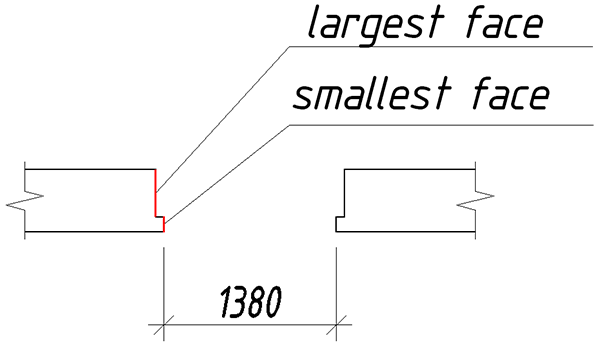
To create exterior dimensions, click Continue. After the command starts, the following prompt appears:
Select walls and grids – select walls and grids on the current plan. An element filter is used during selection, so you can select the entire plan.
For a correct result, the selected walls should form a closed contour whenever possible. If the contour is not closed, the resulting dimensions may differ from what is expected.
If only grids are selected for processing, the dimension chains are created in reverse order, and the offset of the first chain is measured from the outermost point of the farthest grid.
For example, specify the following configuration settings:
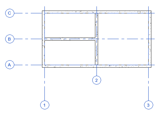
Select the grids on the plan:
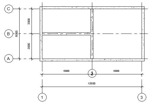
The result is:

 YouTube